Student of Non-violent Communication, researcher, trainer.
Spatial registration of 3D map and stack of slices images
1. Cross-sectional slices are added to existing 3D map, so first, make sure you import or load the map (either load existing workspace file or import CARTO/NavX/Rhythmia/etc. files). Slices images have to be in bitmap (bmp) format (bmp file size is large but this format ensures there is no quality loss during compression).
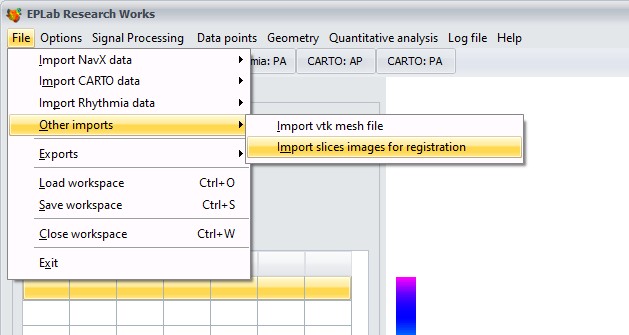
2. To import slices, go to:
App will ask you for inter-images spacing/slice thickness. Default value is 4 mm. This value can be adjusted for every slice later on.
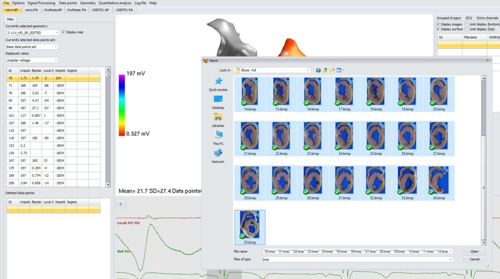
SLICE IMAGES PREPARATION: to achieve best result, make sure that each slice image has no margins (that is, edge of the tissue “touches” edge of image). App stacks images according to their geometrical centers, so margins would result in a shift). Also, make sure that at least one image contains mm scale (e.g. a line of 10 mm length) so that images can be scaled properly.
Select all images you want to import. If there are only bitmap files in the folder, you can use multi-select (Ctrl+A).
Import and processing may take few minutes. Log box will notify when import is completed.
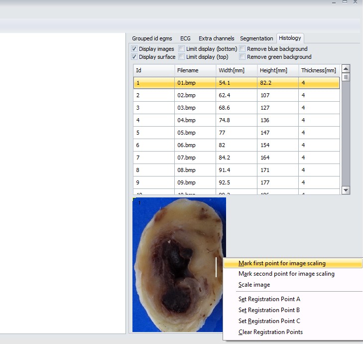
All tools regarding image fusion with EA map are in right panel, under “Histology” page.
3. Once images are loaded, it’s time for scaling the image. First, find the image with a scale (in example below, it is a white line of 10 mm length). Then, right click at the first end of the line and select “Mark first point for image scaling”.
Then, point at the second end of the scaling line, right-click and select “Mark second point for image scaling”. Now, there should be two yellow crosses at both ends of the scaling line. If it is so, right click on the image (anywhere) and select “Scale image”. App will ask what is the actual distance between two marked points. Put the value and click ok. Images widths/heights will be scaled in 3D world to correspond to selected scaling.
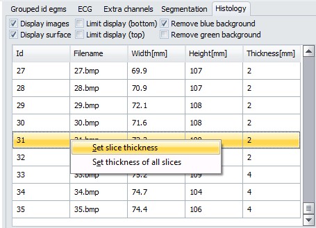
4. Next step is setting slice thickness. From the images list, select a slice and right-click. Then, you can set thickness of all slices at once, or modify just the thickness of selected slice.
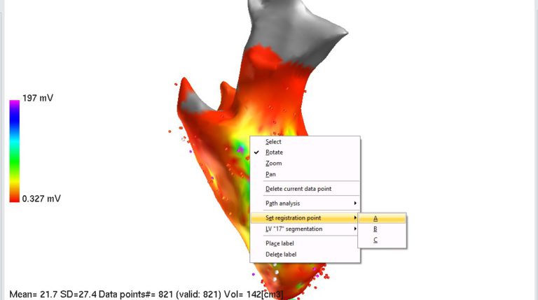
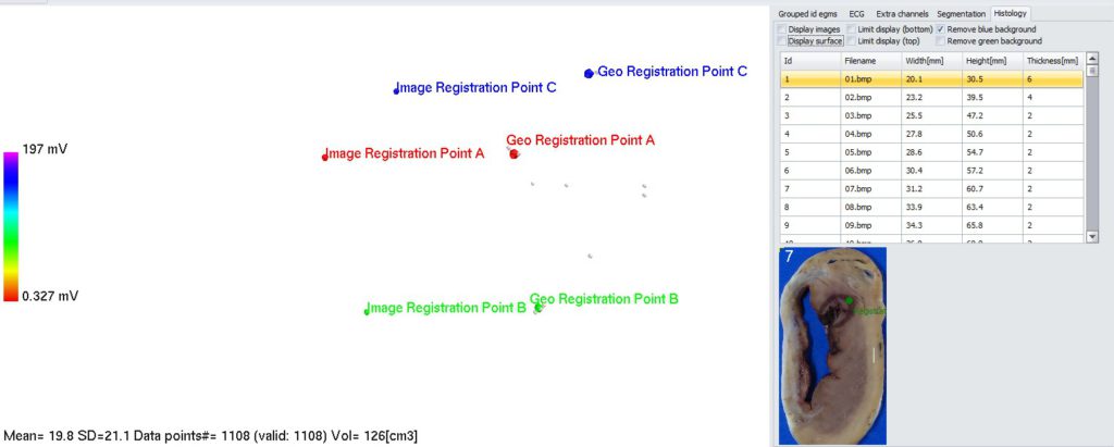
5. Putting registration points onto EA map. To remove display of images in 3D panel, uncheck “Display images” checkbox in Histology panel. You may also want to zoom in EA map to have better view. To put registration point, right click on specific point on EA map and select “Set registration point->A”. Do the same for point B and C.
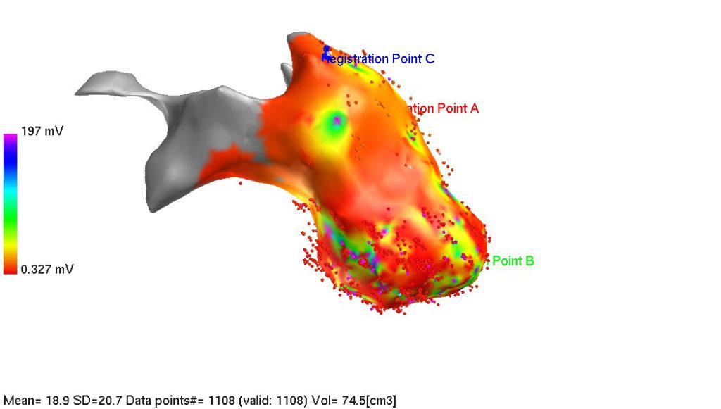
If registration points on EA map are linked with data point id, select desired data point in the list on the left side of the screen. Selected data point will be highlighted on EA map by blue cross (you may have to rotate the map to see it). At the end, you should have 3 registration points on EA map:
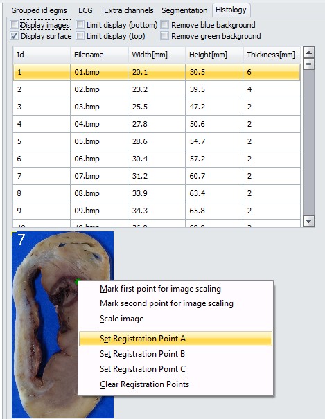
Now, registration points have to be placed on slices. Those spots can be for example ablation lesions or specific anatomical landmark points. Select the slice from the list in “Histology” tab, point at specific site on the slice image below the list and select “Set Registration Point A”. Do the same for point B and C.
Now, having all A, B, C registration points on both EA map and slices images, it’s time for spatial registration.
6. Spatial registration
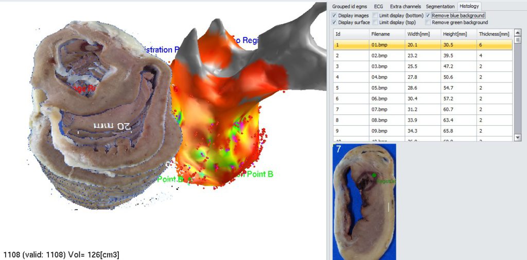
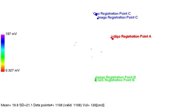
Initially, 3D geometry and slices stack may be shifted in space:
(tip: to remove blue/green background from image, check appropriate checkbox in “histology” tab)
Turn off display of both 3D geometry and slices stack (ucheck appropriate checkboxes in Histology tab).
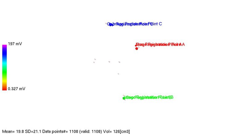
Now you see all triplets of registration points. 3 points based on 3D geometry and 3 points marked on slices images. To start spatial registration process, go to menu and select: “Geometry->Spatial registration->Register current geometry with set of histology slices”. All points should converge to minimize reciprocal distance.
It may happen that tissue shrank before making photos and generating images for integration. In such case, image registration points will be somewhat “interior” with respect to 3D geometry registration points.
To remedy that, use geometry scaling tool. Go to menu: “Geometry->Translate current geometry”. Form will appear asking for specific values. Fill “Scaling for XYZ” fields with desired values (e.g. if you want to decrease 3D geometry size by 80% to better conform with slices images, put 0.8 in each field). And click ok. Geometry will be rescaled, resulting in better alignment of registration points (provided proper scaling coefficient was selected, you may need to experiment a bit to find correct one; once shrinking geometry (scaling coef <1) and then increasing (scaling coef >1)).
Once you are happy with alignment, perform registration step once again (“Geometry->Spatial registration->Register current geometry with set of histology slices”).
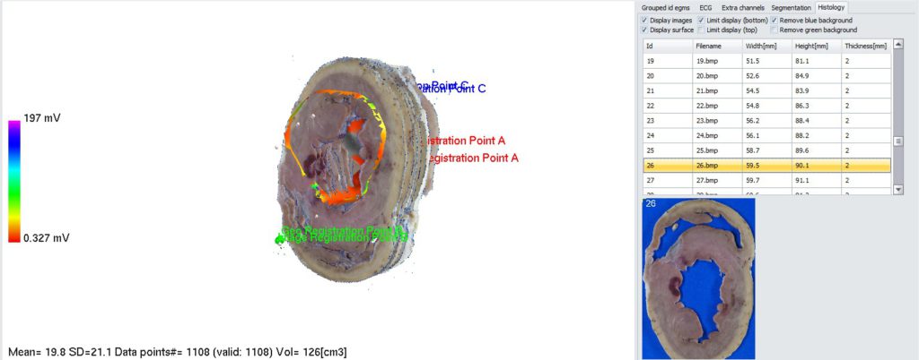
If you want to see cross-section of registered objects, use “Limit display (top)” and “Limit display (bottom)” checkboxes in histology tab. When checked, display will be limited with respect to currently selected image.
7. Placing labels on 3D geometry to identify corresponding site on slices images. To start, in Histology tab uncheck “Display images” checkbox (and “Limit display checkboxes if checked). Make sure “Display surface” is checked. In 3D panel, find a spot of interest and righ-click on it. From context menu, select “Place label”. Dialog box will appear asking what label should be placed. You can select one from the list or add your custom label. Click ok. Label will appear on 3D surface, but also current image will be updated in “Histology” tab. 2D image below the list will contain a label that was placed on 3D geometry (this location on 2D image will be the closest to the 3D label on geometry).
Removing the label from 3D map: right click on label sphere and select “Delete label”.
Tip: don’t forget to save the workspace after you finish (File->Save workspace).